Views: 0 Author: Site Editor Publish Time: 2025-04-24 Origin: Site
The abnormal operating conditions of transformers primarily include overload, overcurrent caused by external short circuits, neutral-point overvoltage due to external ground short circuits, oil level drop from tank leakage, or temperature rise resulting from cooling system failures. Additionally, large-capacity transformers, characterized by their high-rated operational magnetic flux density, may experience over-excitation faults during overvoltage or low-frequency operation, as their operational magnetic flux density is directly proportional to the voltage-to-frequency ratio. To address these conditions, large transformers typically employ the following protection schemes:"
I. Gas (Buchholz Relay) Protection
Protects against internal short circuits and oil level drop in the transformer.
II. Differential Protection & Current Instantaneous Trip Protection
Protects against phase-to-phase short circuits in windings or terminal leads, ground short circuits in high ground fault current systems, and inter-turn short circuits in windings.
III. Overcurrent Protection
Safeguards against external phase-to-phase short circuits and acts as backup protection for gas protection and differential protection (or current instantaneous trip protection).
IV. Zero-Sequence Current Protection
Protects against external single-phase ground short circuits in high ground fault current systems.
V. Overload Protection
Monitors symmetrical overload conditions and actuates an alarm signal only.
VI. Over-Excitation Protection
Prevents transformer over-excitation from exceeding permissible limits.
![]()
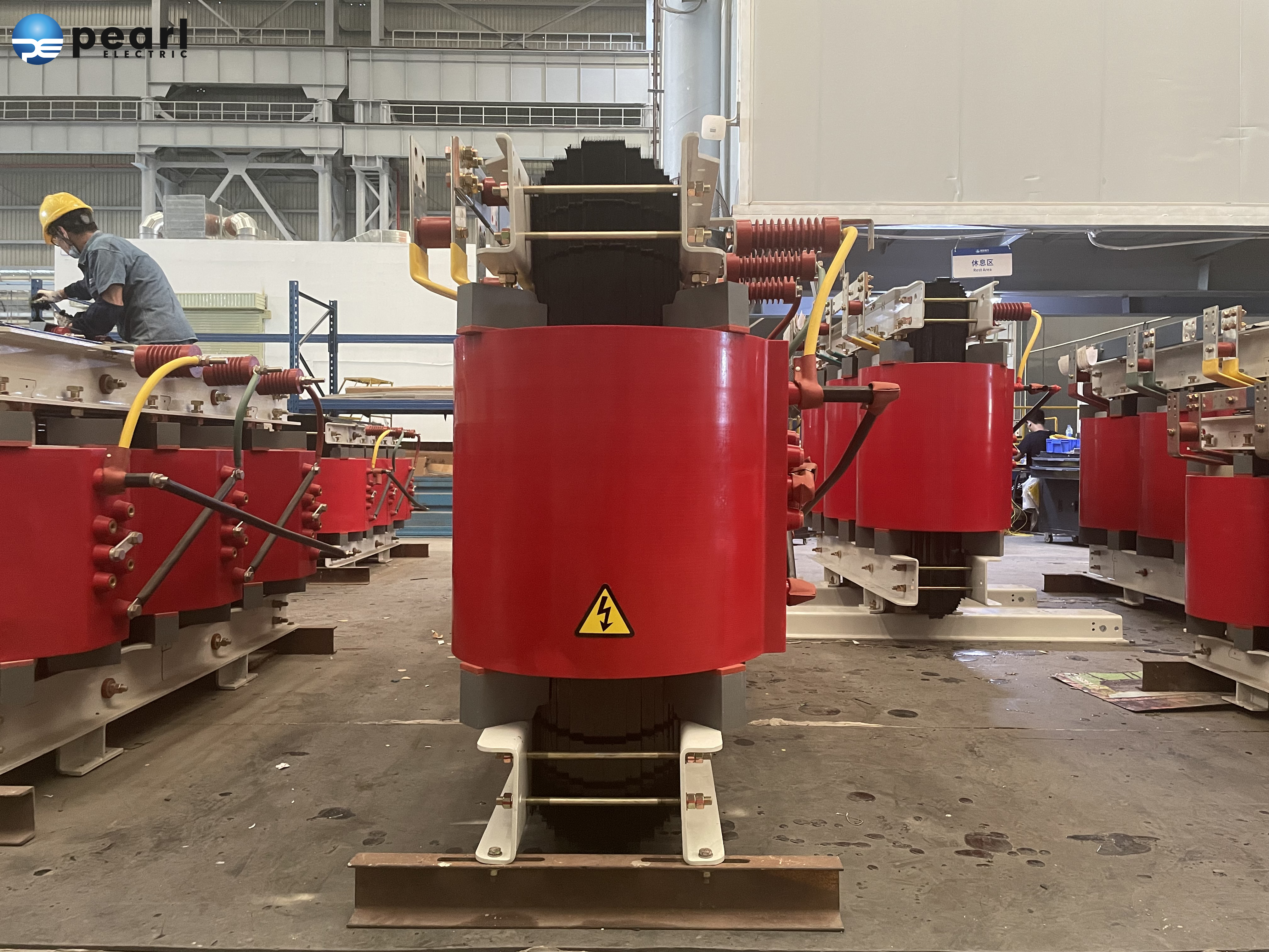
Buchholz relay protection detects various internal faults and oil level reduction in transformer tanks. All oil-immersed transformers rated 0.8MVA and above, as well as oil-immersed transformers rated 0.4MVA and above installed in workshops, shall be equipped with Buchholz relay protection. In the event of minor gas accumulation or oil level drop caused by internal tank faults, the protection shall instantaneously activate an alarm signal. When significant gas generation occurs, the protection shall trip all circuit breakers on all sides of the transformer. Additionally, oil-immersed transformers with on-load tap-changing devices shall also be fitted with Buchholz relay protection.
Longitudinal differential protection or current instantaneous trip protection that responds to short-circuit faults in transformer leads, bushings, and internal windings. The protection shall instantaneously trip all circuit breakers on all sides of the transformer.
1. Current instantaneous trip protection shall be installed for:
Plant service transformers below 6.3MVA operating in parallel
Standby plant transformers below 10MVA operating individually
When the backup protection time exceeds 0.5 seconds.
2. Longitudinal differential protection shall be installed for:
Plant service transformers ≥6.3MVA operating in parallel
Standby plant transformers ≥10MVA operating individually
Transformers ≥2MVA where current instantaneous trip protection fails sensitivity requirements
3. Dual longitudinal differential protection may be installed for transformers with high-voltage side ratings ≥330kV.
4. Generator-transformer unit protection:
With generator-transformer circuit breaker: Separate differential protection for generator
Without generator-transformer circuit breaker:
≤100MVA units: Common differential protection
100MVA units: Common protection + separate generator differential
200-300MVA units: Optional dedicated transformer differential protection (dual high-speed protection)
Protection against external phase-to-phase short circuits in transformers, serving as backup to Buchholz relay protection and longitudinal differential protection (or current instantaneous trip protection), including:
· Overcurrent Protection
· Low-Voltage Activated Overcurrent Protection
· Composite Voltage-Activated Overcurrent Protection
· Negative-Sequence Current Protection
· Impedance Protection
The protection system shall operate with a time-delayed tripping of all circuit breakers.
1. Overcurrent Protection is recommended for step-down transformers.
2. Composite Voltage-Activated Overcurrent Protection should be applied to:
Step-up transformers
System intertie transformers
Step-down transformers where standard overcurrent protection fails sensitivity requirements
3. Negative-Sequence Current Protection and Single-Phase Low-Voltage Activated Overcurrent Protection may be used for step-up transformers rated ≥63MVA.
4. Impedance Protection may be employed when the protections listed in Items 2 and 3 cannot meet sensitivity or selectivity criteria.
Zero-sequence current protection for detecting external ground faults in transformers within effectively grounded systems. In power systems rated 110kV and above with effective grounding, where transformers may operate with neutral grounding, zero-sequence current protection shall be installed for step-up/down transformers with power sources on two or three sides. This protection serves as backup protection for the transformer's primary protection and adjacent components.
Zero-sequence current protection refers to a protection device that operates based on zero-sequence currents generated during ground faults. In cable circuits, dedicated zero-sequence current transformers (ZCTs) are employed to implement ground fault protection. The ZCT is installed around a three-core cable, with the current relay connected to its secondary winding.
![]()
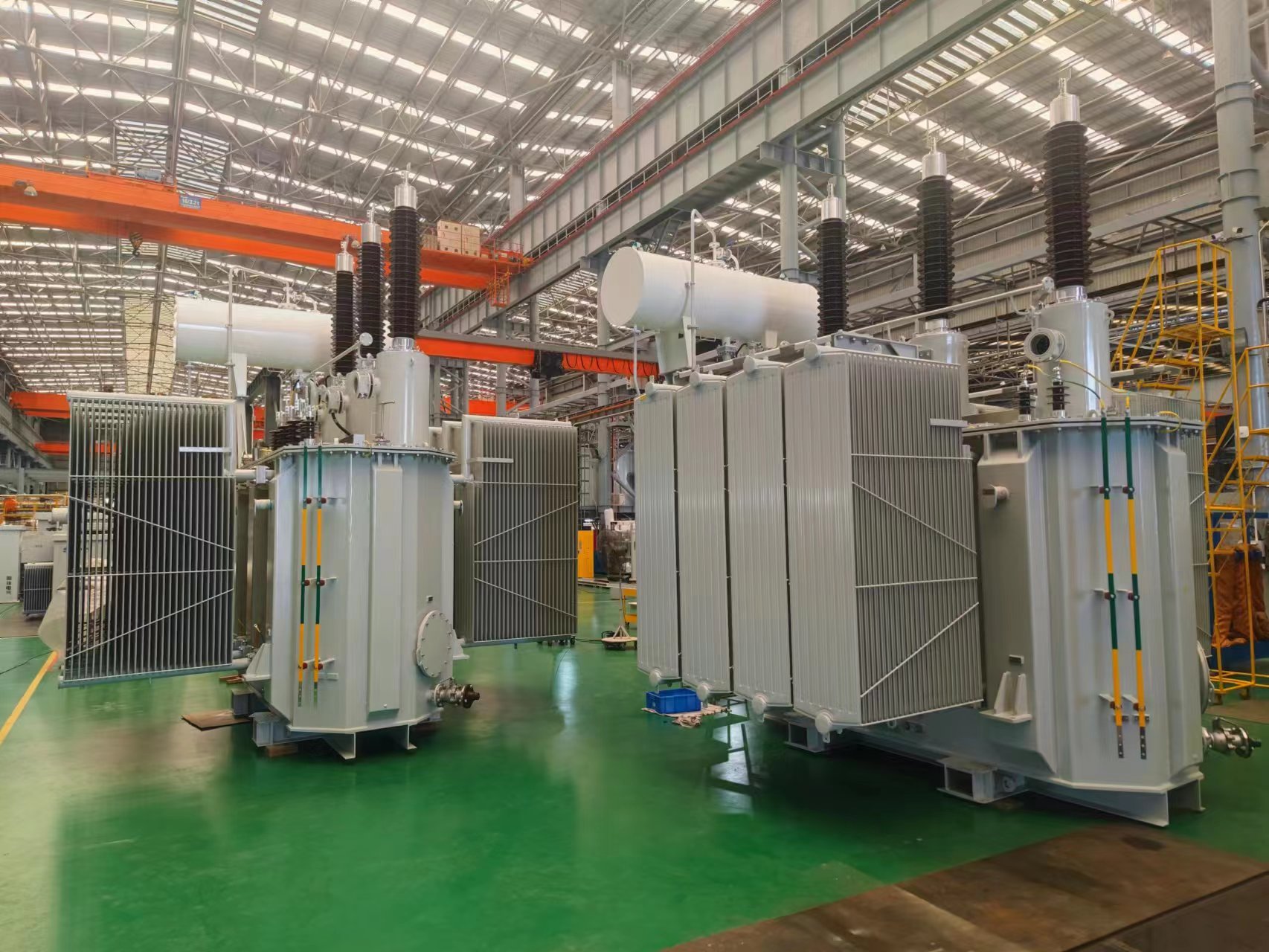
For transformers with a capacity of 400kVA and above, when operating in parallel or separately as backup power for other loads, overload protection should be installed according to possible overload situations. For autotransformers and multi winding transformers, the protection device should be able to reflect the overload situation of the common winding and each side.
In most cases, the overload current of a transformer is symmetrical in three phases, so overload protection only needs to connect one phase current, use a current relay to achieve it, and apply a certain delay to the signal. When choosing which side to install the protection on, it should be considered that it can reflect the overload situation of all coils on all sides of the transformer. In substations without regular duty personnel, overload protection can be activated to trip or disconnect partial loads when necessary.
In the current design of large transformers, in order to save materials, reduce costs, and reduce transportation weight, the rated working magnetic flux density of the iron core is designed to be relatively high, about 1.7-1.8 T, close to the saturation magnetic flux density (1.9-2 T). Therefore, under overvoltage conditions, it is easy to generate over-excitation. Due to the relatively "hard" magnetization curve, during over-excitation, the excitation impedance decreases due to iron core saturation, and the excitation current increases rapidly. When the working magnetic density reaches 1.3 to 1.4 times the normal magnetic density, the excitation current can reach the rated current level.
Secondly, due to the fact that the excitation current is non-sinusoidal and contains many high-order harmonic components, the eddy current losses of the iron core and other metal components are proportional to the square of the frequency, which can cause severe overheating of the iron core, metal components, and insulation materials. If the over-excitation factor is high and the duration is too long, it may damage the transformer. Therefore, transformers with a high
voltage side of 500kV should be equipped with over-excitation protection.
The purpose of installing transformer over-excitation protection is to detect the over-excitation situation of the transformer, promptly issue signals or act on tripping, so that the over-excitation of the transformer does not exceed the allowable limit, and prevent damage to the transformer due to over-excitation.